Introduction
This is the documentation of the 3ds to Re-Volt exporter. (add image)
Please note that it is currently uncomplete ! It is updated regularly. Some parts will most likely be moved or renamed.
Green text is used as personal notes for further editing ! ![]()
In the meantime, feel free to ask for a specific part or more informations ! Also if you see something wrong, please let me know.
Please note that some parts of this documentation are separate tutorials.
How to use ?
- Installation (todo : make separate – change exporter page too)
- Download and install
- 3ds max setup
- Export process
- What can this exporter do ?
- How can I make a track or a car ?
- What are PRM, W and RIM files ?
- PRM: Instance file
- W: World file
- RIM: Mirror file
- What can this exporter do ?
- Exporter panels
- Utilities
- Vertex channel display
- Materials
- Backface culling
- Hidden edges
- Cleanup objects
- Cleanup geometry
- Search for “Zero edge”
- Quick Smoothing Groups
- Smoothing Groups panel
- Surface properties
- Collision properties
- Visual Properties
- Convert ASE2RV objects
- Exporting an instance (PRM file)
- User Interface explained
- Export options
- Fine tune
- Export guidelines
- User Interface explained
- Exporting a track (W file)
- User Interface explained
- Export options
- Fine tune
- Mirrors
- Texture Animations
- Helpers
- Export guidelines
- Texture animations and mirror planes
- User Interface explained
- Exporting mirrors (RIM file)
- User Interface explained
- Export options
- Mirrors
- Infos
- Export guidelines
- Good practice
- Common good practice examples
- User Interface explained
- Utilities
- Modeling basics
- Texturing basics
- Surface properties
- Vertex colors
- What are vertex colors, how does it work ?
- How to assign colors
- Using the Edit_Poly
- Using the Vertex Paint modifier
- Using lights
- Lighting
- Envmapping
- Transparency
- Advanced modeling
- Texture animation
- Mirrors
- How does it work ? (describes export steps)
- What does this mean index (for anything you didn’t understand)
Installation
Download and install
To install, just download the latest version from the download page, and drag and drop 3ds2rv.mzp in the 3ds max viewport.
You need to drag and drop the 3ds2rv.mzp file over a running instance of 3ds max and follow the instructions.
Installation routine is shown in the following video:
3ds max setup
Complete tutorial here :
Basic setup is shown in the following video:
export process
What can this exporter do ?
This tool can create files for Re-Volt :
- cars (body and wheels)
- track scenery (main world, instances and mirrors)
add image of car + wheel + track or instance…
There are other tools you may want to have a look at :
- Rvtmod7 package (add link & description)
- Blender exporter (add forum link)
- (Other tool I saw on a forum ?)
How can I make a track or a car ?
This tutorial is not meant to explain how to create a car or a track, if you want to know more about this please check one of these :
- track creation tutorial (currently under creation)
- car creation tutorial (not started yet)
However, if you want to create one of these you’ll need to export a 3d model into the game. Here are the different files required :
- cars (body and wheels) : one *.prm file for the car body, and one or more *.prm files for the wheels
- track scenery (main world) : one *.w file for the track scenery, and one *.ncp file for the collision
- track scenery (instances) – optional : one or more *.prm files for instances, with or without *.ncp associated files for their respective collision
- track scenery (mirrors) – optional : one *.rim file
There’s more files required, but these are the files you can create using the exporter. For more information please refer to the tutorials above.
What are PRM, W and RIM files ?
PRM: Instance file
add image of an instance (garden plant ?)
A *.prm is a single object. It is used in game for car models, wheels and also in tracks as instances. For example, if you have a plant you want to place several times in your track, you can turn it into an “instance” (i.e. an object you can duplicate across the track using the ingame editor). It can be instanciated, moved and rotated, so with only a few objects (or instances) you can build a complete track, thus reducing file size ! Instanciating objects in a track will use another file created by the ingame editor: the *.fin file. This file stores position and rotation values for each instance.
More infos about the ingame editor : the “makeitgood” cheatcode. (link doesn’t point anywhere)
An object is stored as a *.prm file. If the object has collision properties, a separate *.ncp file using the same filename is required (so if your object is named “myobject.prm”, the collision file must be named “myobject.ncp”).
Note that if you put an object in an empty track, your car will not collide with the object even if there’s a *.ncp file associated, UNLESS it is inside the track collision bounding box (a box that surrounds everything). The track collision is defined in the track *.ncp file.
![]() Be careful not to use the same filename for an object as the track world filename since both are using a *.ncp associated file.
Be careful not to use the same filename for an object as the track world filename since both are using a *.ncp associated file.
W: World file
add image of some track…
A *.w is the track world file. It can contain multiple objects and have more advanced informations than a simple object file, like texture animations.
A world file is stored as a *.w file. There MUST BE a collision file too, saved in a separate *.ncp file using the same filename (so if your track is named “mytrack.w”, the collision file must be named “mytrack.ncp”).
RIM: Mirror file
add image of a mirroring plane
A *.rim file contains mirroring surfaces. The mirrors are only flat rectangles aligned on X and Z axis (in Re-Volt game, Y is the vertical axis, and XZ is the ground plane).
A mirror file is stored as a *.rim file. It must use the same filename as the track world file it is designed for (so if your track is named “mytrack.w”, the mirror file must be named “mytrack.rim”).
Exporter panels
Utilities
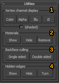
1. Vertex channel display
This allows to easily change display mode for any selected object into the scene.
- Color, Alpha and Illu: display vertex colors, vertex alpha or vertex Illumination channel respectively
- 4th button reset display to default
- (shaded): display vertex channel and shade using default viewport shading. Shaded option may cause strange results in latest 3ds versions…
If nothing happens please see 3ds display setup tutorial.
2. Materials
Select an object to show or hide the material.
- Show/Hide: affect the material itself, so if it is shared through the scene it will affect display of every object using it.
- Remove: remove the material from selected object only.
3. Backface culling
Backface culling On/Off. This is VISUAL ONLY !
- Single sided: backface cull On
- Double sided: backface cull Off
4. Hidden edges
Hidden edges will show every single triangle used to render the mesh. 3ds max allow to work with n-gons, meaning you can create faces with 4 sides, 5 sides,… up to n sides. But no matter how much sides, every face is still a group of multiples triangles that are not displayed by default. Re-Volt engine only support triangles and quads (3 and 4 sided faces). Try to work only with such faces.
When working with quads, you’ll sometime need to “turn” the hidden edge. It can be done using the Edit_Poly modifier but only one by one. In case you have to turn a lot of edges, you can select every quad you want to affect and use the “Turn” button while still having the object selected. 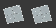 This is working with several Edit_Poly objects selected ! (see modeling chapter and texture animations chapter to see possible uses (add links))
- Show: show hidden edges
- Hide: hide hidden edges
- Turn: turn hidden edges of every selected quad of every selected object
Cleanup objects
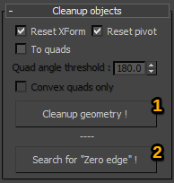 1. Cleanup geometry
This help optimizing geometry for export.
- Reset XForm: apply a transformation reset (meaning rotation values will be 0,0,0 and scale 1,1,1)
- Reset pivot: center the pivot
- To quads: convert every face with more than 4 sides to triangles, leaving only triangles and quads.
- Quad angle threshold: maximum allowed angle between the 2 triangles forming a quad.
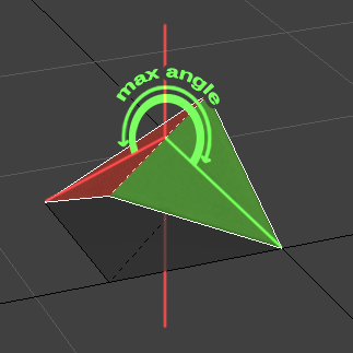 A value of 180 will keep every quad, 0.001 will keep only flat quads.
 - Convex quads only: every quad will be converted to triangles if not convex (non-convex quads may lead to strange artifacts like collision bugs or visual glitches, particularly when playing a mirrored track)
2. Search for “Zero edge”
Sometimes after export unexplained visual bugs appears (distorted envmap, invisible collision wall…) that may be caused by edges that have a length of zero. To solve the problem you need to find the guilty “Zero edge”.
You may try to see where the problem lies by looking at the object from “behind” : if you correctly welded all the vertices, there should be no visible edge (note that you must turn on backface culling AND use another renderer than “nitrous”). If there is, the guilty one is propably at one of the end. Try to move a vertex and see if there’s something wrong.
The “Search for Zero edge !” button may help finding the culprit faster, but for now it fails to recognize an “Hidden edge” as a “Zero edge”. Select the objects to export and click “Search for Zero edge !”. If any zero edge is found the concerned object it will be automatically selected.
If a “Zero edge” is found, select all vertices and use “weld” with a very low value. If the “Zero edge” is an “Hidden edge”, you have to find a workaround. Converting the “Hidden edge” to a normal one may help.
Quick Smoothing Groups
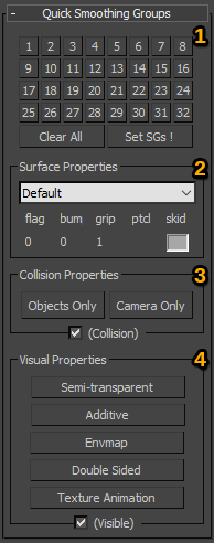 1. Smoothing Groups panel
This is the standard panel you can find in the Edit_Poly modifier to set or unset Smoothing Groups. Checking values here will reflect the properties you’ll get in Re-Volt.
- Clear All: unset every Smoothing Group on the panel
- Set SGs: apply current panel to selected objects (currently not working)
2. Surface properties
Surface properties are used to change the surface type in Re-Volt.
- flag: “surface flag” the original id number in the Re-Volt engine
- bum: “bump value” bump value of the surface (0 to 2)
- grip: “grip value” grip value of the surface (-5 to 3)
- ptcl: “particle color” if used, particle color
- skid: “skid color” if used, skid color
3. Collision properties
- Objects Only: only objects will collide with the surface. i.e. cars, weapons and objects like basketball, cone, bottle… Possible use: transparent surfaces, surface just under the road (camera bug when repositionning car).
- Camera Only: only camera will collide with the surface
- (Collision): uncheck if you dont want the surface to be solid (like water surface)
4. Visual Properties
- Semi-transparent: this is NOT to activate transparency. Semi-transparency is useful used in combination with mirrors as it is the only surface that will NOT be mirrored. You may apply transparency too but you can’t have fully transparent surface.
So where’s the standard transparency mode ?? ![]() See Vertex colors chapter !
See Vertex colors chapter !
- Additive: this will turn the surface to an additive transparency mode. Instead of just applying transparency, the colors will be added to what’s behind. It can create great glowing effects such as fire or neons… -additive thing image here-
- Envmap: this will activate the “Glossiness”, “Environment mapping”, “Shininess” effect, however you name it.
 See vertex colors chapter for more info.
 - Double Sided: if you turn this On, the surface will be visible from both side in Re-Volt. Note that this is VISUAL ONLY !
- Texture Animation: the surface will not display as in 3ds max anymore. Instead, it will use any texture animation exported within the track and this will change the way the material ID is used !!
 See texture animation chapter. If no texture animation is exported, nothing will change.
 - (visible): uncheck if you dont want the surface to be visible. (like an invisible wall)
Convert ASE2RV objects
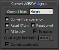 You may have heard about the ASE2RV tools. These tools can convert objects to Re-Volt from an ASCII file format (*.ase files). There where created waaay before this exporter and are lacking some functionnalities. You may still find these here -insert download or link here- and use them. The way surface properties were set is almost the same using the Morph option, and a bit different using the Ali option. This tool will simply convert any property applied to fit the exporter’s needs. Cleanup options are present too (see Cleanup objects panel for more infos about the options). -verify Semi-Transparent property vs transparent in script-
Exporting an instance (PRM file)
User Interface explained
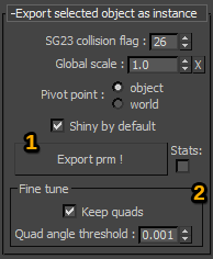
1. Export options
- SG23 collision flag: any polygon with Smoothing Group 23 applied will be assigned the surface property defined by the flag number here. See Smoothing Group conversion table to see the different flags.
- Global scale: scale factor. The scale center is defined below. A scale of 1.0 will not modify anything. A scale of 0.5 will make the object half the original size, a scale of 2.0 will make the object twice the scale.
- Pivot point: use object pivot point or world origin (coordinates: 0,0,0)
- Shiny by default: if no polygon with Smoothing Group 30 applied is found (Envmap On), every polygon will have Envmap On. This does not mean that the object will be shiny ingame since you have to turn on the property ingame too !
- Export prm: click to export the selected object as an instance. Files created are *.prm (instance visual mesh) and *.ncp (instance collision mesh)
- Stats: display some statistics after export. This may slow down a little the export process.
2. Fine tune
- Keep quads: keeping quads will help reduce the number of polygons ingame. If you have bugs or glitches you can’t fix, try to turn off. Turning off will export only triangles.
- Quad angle threshold: (visual only) maximum allowed angle between the 2 triangles forming a quad.
 Increasing this value will help reduce the number of polygons exported but if the value is too high you may see visual glitches (polygons will sometimes disappear). Note that double sided quads will not be affected by this value. A value of 180 will keep every quad, 0.001 will keep only flat quads.
Export guidelines
Select the object you want to export, and click the export button.
You can only export one object at a time.
add a diagram image with 1 input: 1 mesh/poly/primitive, export button and 2 outputs: prm, ncp
Exporting a track (W file)
User Interface explained
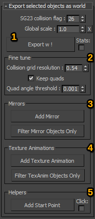 1. Export options
- SG23 collision flag: any polygon with Smoothing Group 23 applied will be assigned the surface property defined by the flag number here. See Smoothing Group conversion table to see the different flags.
- Global scale: scale factor. The scale center is the world origin (coordinates 0,0,0). A scale of 1.0 will not modify anything. A scale of 0.5 will make the track half the original size, a scale of 2.0 will make the track twice the scale.
- Export w: click to export the selected objects as a track. Files created are *.w (track visual meshes) and *.ncp (track collision meshes) and if there is some mirror planes a *.rim file too.
- Stats: display some statistics after export. This may slow down a little the export process.
2. Fine tune
- Collision grid resolution: collision polygons are indexed in a flat grid. If you create only large polygons, the grid squares will be large so the grid will be simple (like 2×2), and if you create small polygons, the grid squares will be small so the grid will be more complex (like 100×100). The file size will be larger if the grid is complex, but if the grid is too simple the game may run slower. By default the value should be ok, try can play with it to see what it does (turn on Stats).
- Keep quads: keeping quads will help reduce the number of polygons ingame. If you have bugs or glitches you can’t fix, try to turn off. Turning off will export only triangles.
- Quad angle threshold: (visual only) maximum allowed angle between the 2 triangles forming a quad.
 Increasing this value will help reduce the number of polygons exported but if the value is too high you may see visual glitches (polygons will sometimes disappear). Note that double sided quads will not be affected by this value. A value of 180 will keep every quad, 0.001 will keep only flat quads.
3. Mirrors
- Add Mirror: turns the cursor into select mode. Click on the object you want to be a mirror. Note that the object will not be visible ingame as it is turned into a mirror plane. Object needs to be an Edit_Poly.
 See mirrors chapter for more informations.
 - Filter Mirror Objects Only: select all visible objects that have mirroring properties in the scene.
4. Texture Animations
- Add Texture Animation: turns the cursor into select mode. Click on the object you want to be a texture animation reference. Note that the object will not be visible ingame. Object needs to be a quad Edit_Poly.
 See texture animations chapter for more informations (add link).
 - Filter TexAnim Objects Only: select all visible objects in the scene that have texture animation properties.
5. Helpers
- Add Start Point: creates a small helper to place on the start grid. In the modifier panel you can see and copy values for your track *.inf file.
 See tutorial about track creation.
Export guidelines
Select the object(s) you want to export, and click the export button.
You can export as many objects as you want.
The world exporter can also export mirror planes at the same time. This means that there will be a *.rim file created along with the *.w and *.ncp files, all sharing the same filename.
add a diagram image with 1 input: multiple meshes/polys/primitives, export button and 3 outputs : w, ncp, rim
 Texture animations and mirror planes
If you have texture animation and/or mirrors, add the reference objects to the export selection ! These are only references ![]() they will not be exported as visible geometry !
they will not be exported as visible geometry !
- Texture animation references will not be visible in the game. (See texture animation chapter for more informations (add link)).
- Mirrors will not be exported as visible geometry but as mirror planes. (See mirrors chapter for more informations (add link)).
Exporting mirrors (RIM file)
User Interface explained
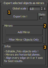 1. Export options
- Global scale: scale factor. The scale center is the world origin (coordinates 0,0,0). A scale of 1.0 will not modify anything. A scale of 0.5 will make the mirrors half the original size, a scale of 2.0 will make the mirrors twice the scale. Try to match the scale factor you used for world export if you’re exporting mirrors separately.
- Export rim: click to export the selected objects as mirror planes. Files created is *.rim (mirror planes).
- Stats: display some statistics after export. This may slow down a little the export process.
2. Mirrors
- Add Mirror: turns the cursor into select mode. Click on the object you want to be a mirror. Note that the object will not be visible ingame as it is turned into a mirror plane. Object needs to be an Edit_Poly.
 See mirrors chapter for more informations (add link).
 - Filter Mirror Objects Only: select all visible objects in the scene that have mirroring properties.
3. Infos
- This is just a reminder: objects used to make mirrors should be made only from flat quads aligned on the XY grid (see below).
Export guidelines
Select the object(s) you want to export, and click the export button.
You can export as many objects as you want. It will create a *.rim file. If you want it to be useful, you should give the same file name as the track one (the *.w file).
Good practice
Note that even if you can make anything to make a mirror, the exporter will reduce polygons to FLAT RECTANGLES ONLY.
Exporting a triangle will result in a flat rectangle surrounding the triangle. That’s why it is better to USE ONLY FLAT QUADS when modeling mirror objects.
![]() Note that the edges of the quads should be aligned on either X or Y axis in 3ds max. By working like this, the mirror planes in Re-Volt will be exactly the same as in 3ds max.
Note that the edges of the quads should be aligned on either X or Y axis in 3ds max. By working like this, the mirror planes in Re-Volt will be exactly the same as in 3ds max.
Try to avoid creating mirrors on top of each other, or at least not too close.
If you dont follow these guidelines, there can be multiple overlapping mirror planes in the game that may cause visual glitches.
Common good practice examples
- image triangle with resulting mirror should be a quad -
- image 2 triangles forming a quad should be a quad - if not 2 overlapping mirror planes.
- image not XY aligned quad with resulting mirror -
- image not flat plane with resulting mirror -
- image plane on top of another and too close should be avoided -
modeling basics
primitives, edit_mesh and edit_poly.
texturing basics
using a sub-material.
UVW mapping and unwrapping
surface properties
assigning Smoothing Groups
Smoothing Groups conversion table
Conversion table
vertex colors
What are vertex colors, how does it work ?
Vertex colors are mainly used in Re-Volt to create some lighting, transparency or shade the environment mapping effect.
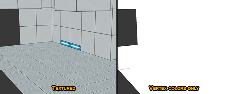
Here you can see how it looks like when no vertex colors are applied to a model:
And then after the scene was lit:
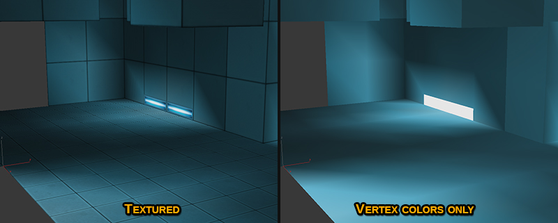
The only difference between the 2 models are vertex colors.
You can see that without any color applied we need some textures to see something. On the 2nd screenshot, even without textures it’s possible to see where to go !
So how does this work ?
You can apply a color on each vertex or face. Here the vertices have been colored to a blueish color with some variations in luminance and tint.
Each vertex have white color by default. It is then multiplied by the texture color (if there’s a texture). All you have to understand is that multiplying by a white color will change nothing so you’ll see the texture as is, multipliying by a black color will give a black output. Anything inbetween will be the texture multiplied by the color.
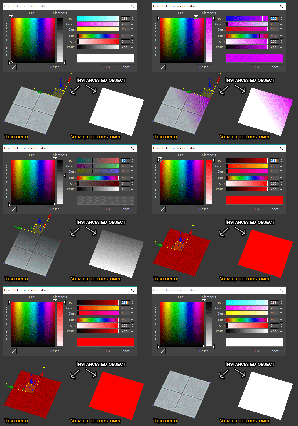
How to assign colors
On a technical side, there are only 2 ways to apply vertex colors !!
Colors can be either applied by vertex or by face. So what’s the difference ?
Using only faces you can create sharp edges:
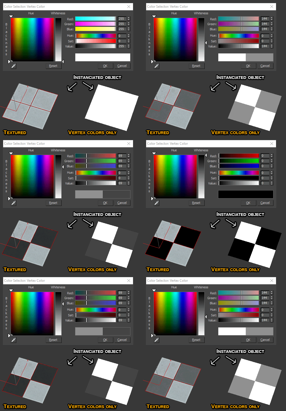
Using only vertices you can create smooth gradients:
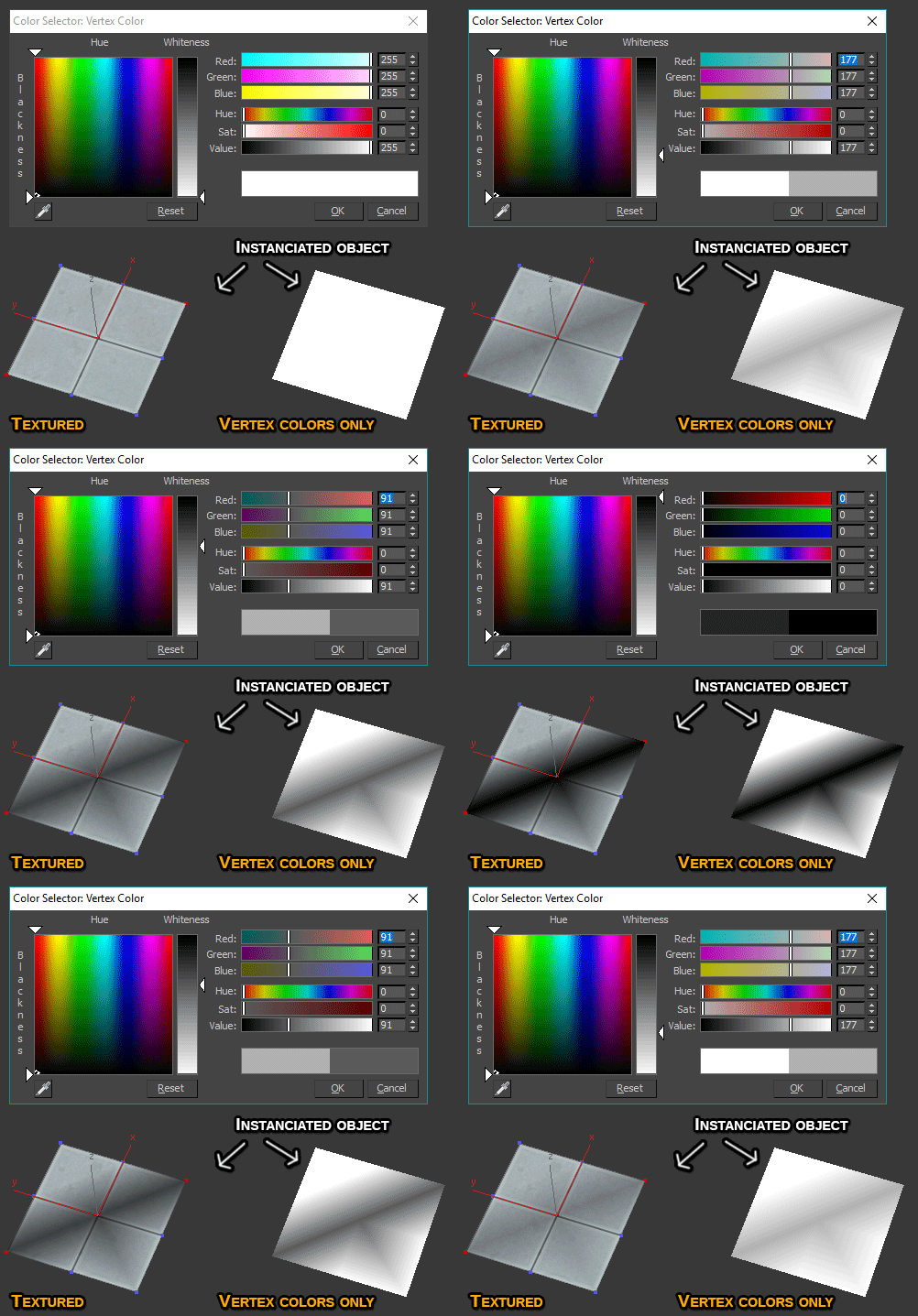
And mixing the two you can achieve interesting results:
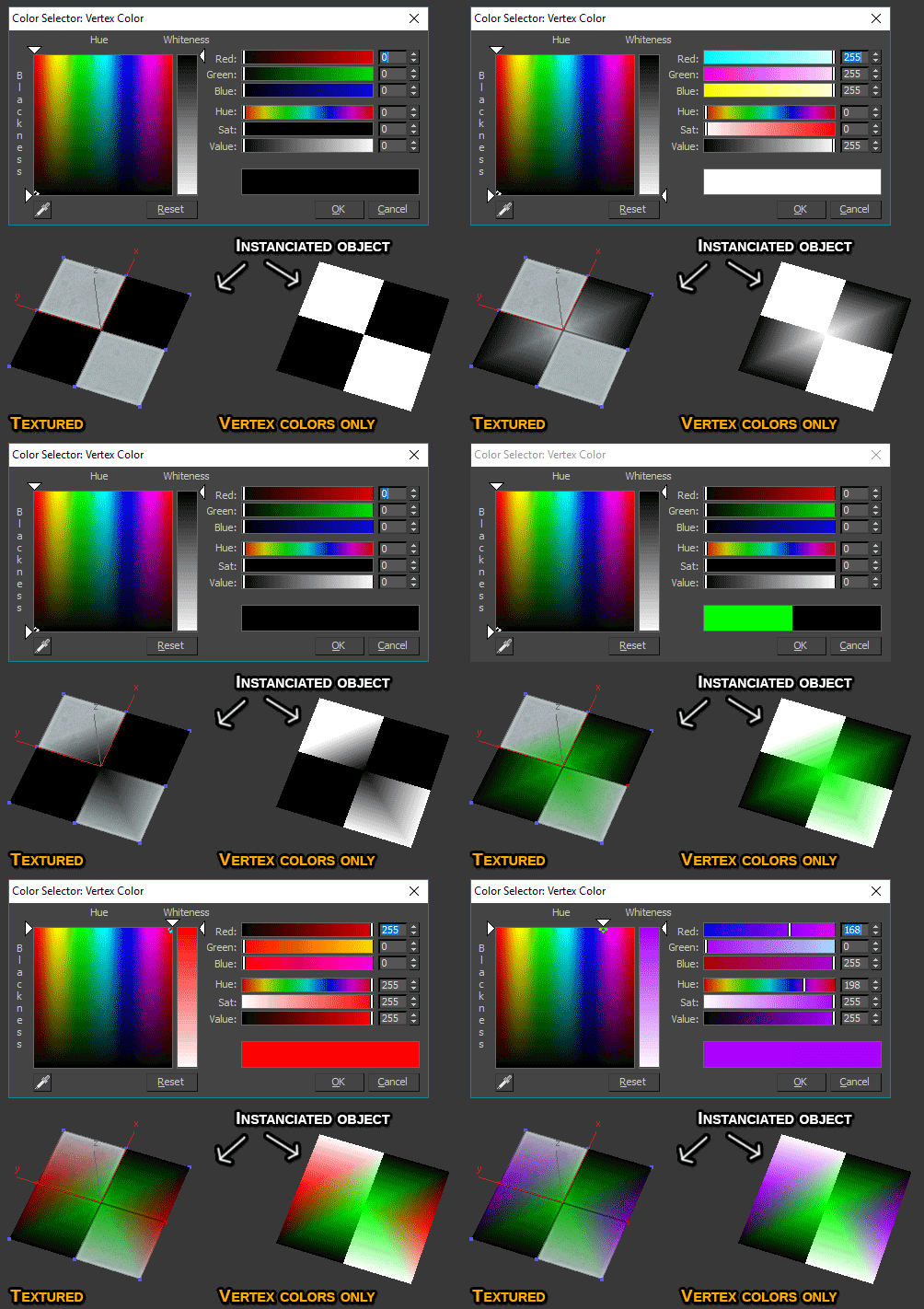
There are 3 different color channels you can use easily:
- Vertex color channel
- Vertex alpha channel
- Vertex illumination channel
There’s no real difference between the 3 in 3ds max, but for the exporter’s needs, here’s what you have to remember:
- Color channel is used to tint polygons. You can apply any color with any method you like.
- Alpha channel is used to create transparency, so working with colors makes no sense here. Only shades of grey are useful (see transparency chapter (add link)).
- Illumination channel, despite it’s name, will not be used to illuminate the polygons but rather to tint the envmap. It is better to apply color by face only (see envmapping chapter (add link))
Now that you know the basics of vertex colors, let’s see how to apply colors inside 3ds max.
Using the Edit_Poly
This is the most basic way to go but it’s fast and easy !
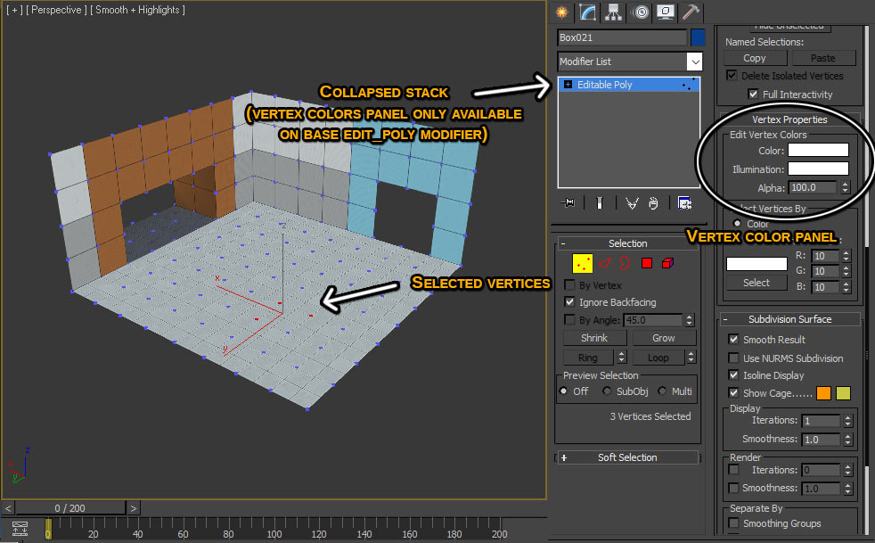
All you have to do is turn you mesh into an Editable Poly (an Editable Mesh would work too but it’s not recommended). Also remember to collapse the modifier stack !! Vertex colors can only be applied on the base object… wich should be an Editable Poly now !
Now that everything is set, turn the Edit_Poly modifier into vertex sub-object mode. This is what you should have:
In the image above, you can see there are 3 selected vertices. You can apply vertex colors using the small panel on the right.
Here we can find our 3 channels:
- Color (with a color picker)
- Illumination (with color picker)
- Alpha (note that there’s only a slider instead of a color picker: that because we’re working in greyscale mode)
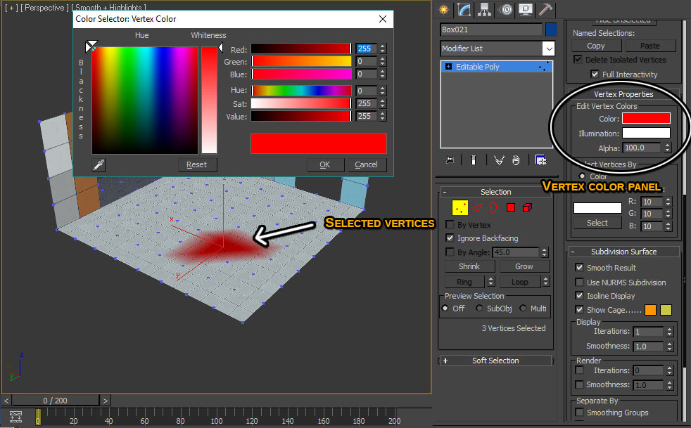
Now you can apply color to the selected vertices. This is an example using a red color:
As stated earlier, there are 2 ways to apply colors : by vertex, and by face.
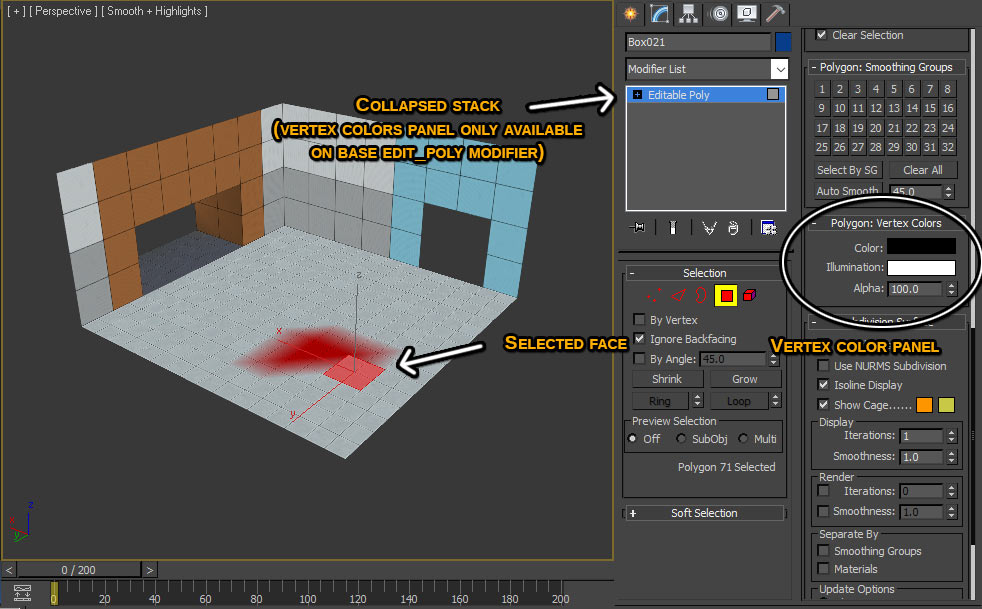
Try to change sub-object mode to face and select a face:
Now you can see we can find the 3 channels again:
- Color (with a color picker)
- Illumination (with a color picker)
- Alpha (note that there’s only a slider instead of a color picker: that because we’re working in greyscale mode)
You may notice that sometimes the color picker changes to black even if the selected face(s) or selected vertices are not black. This is because the color of the multiple affected vertices are not equal ! So if one side of a face is red (like here) and the other white, the color picker turns to black.
This is an example using a blue color:
Note that by default the selected face is red so you cant see the color underneath. Just press F2 to toggle selection display…
And there you go.
- To apply a color in the Color channel, just use the Color color picker
- To apply a color in the Illumination channel, just use the Illumination color picker (see envmapping chapter (add link))
- To apply an alpha value, just change the alpha value (see transparency chapter (add link))
To see the effect when applying something else than color, use the “Vertex channel display” in the “Utilities” panel of the exporter
Using the Vertex Paint modifier
Using lights
Lighting
Simple lighting
Light must be more bright than illuminated surface
Blurry / Sharp shadows
Ambiant occlusion
Using vertex color channel
Envmapping
What is EnvMapping, how does it work ?
How to enable EnvMapping.
Using vertex illumination channel
Difference between vertex colors and envmapping : color stored by polygon
Transparency
What is Transparency, how does it work ?
How to enable/disable transparency.
Using vertex alpha channel
Side note : transparency dont affect EnvMap.
Avoid full transparency, unless needed. Use the “(visible)” checkbox in Visual properties panel instead.
Advanced modeling
Zero edge bug and convex surfaces. Problems that may only occur in mirrored mode.
Texture animation
Understanding basics of texture animation : UVs are modified, not the textures.
You may store a texture animation in an object to use it on other surfaces. You can’t animate UVs directly on the object you want to export.
Plan how many animation references you’ll need.
Animate UVs using UVWmap, UVWunwrap.
Animate material ID using Material modifier.
Create compound animations (animations that must be on several polygons together). How, and Why !
Mirrors
How does it work ? (describes export steps)
Init : sorting objects : Meshes, Polys and Texture animations.
Cleaning objects
Converting objects
Processing collision data
Processing texture animation data (if needed)
What does this mean index (for anything you didn’t understand)
About geometry:
- Bounding Box: the surrounding box of something
- Vertex: a point in space
- Edge: a line linking 2 vertices
- Triangle: a face with 3 edges
- Quad: a face with 4 edges (so in fact 2 triangles “welded”)
- Polygon: a face with 3 or more edges (so in fact 1 or more triangles “welded”)
- Hidden edge: an invisible edge defining the real triangles of a Quad or Polygon (the “welding edge”)


